Writing a Custom Rendering Shader Using Geometry Program
This tutorial focuses on the creation of a GLSL based material that is using geometry shaders. In the OpenGL rendering pipeline, geometry shaders are called after vertex shaders and before pixel shaders (see The GPU Programming Pipeline).
The principle of this material is to show the mesh facets without having to reorganize the geometry. In HOOPS Luminate, meshes are using indexed datasets that cause a mesh vertex to be shared by all its neighboring triangles if that mesh is smooth around that vertex.
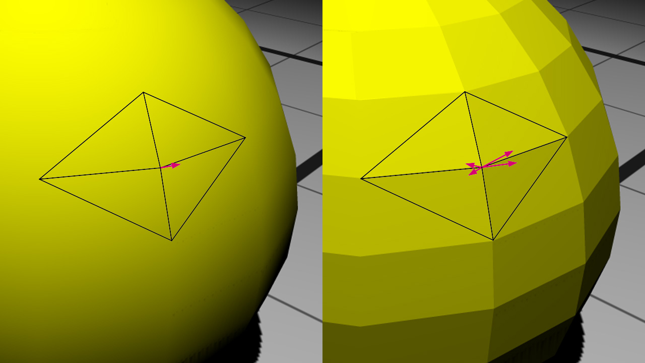
Shared vertices on the left, facettized mesh on the right with exploded vertices
On the left, one single vertex needs to be stored with one normal for the purpose of the surface shading. On the right, to be able to show a facettized view of the model, we need exactly three vertices for each triangle in the mesh. This has a cost and this forces a change in the mesh data organization just for the purpose of showing mesh facets.
Geometry shaders are a convenient and elegant way to dynamically change the organization of the data during the rendering.
During this tutorial, we will apply the created material to a sphere contained in our well-known basic scene.
The Facetted Shader
All the shaders in this tutorial are written in GLSL. Note that if we go for GLSL, all shaders have to be in GLSL. If we have some shaders in ARB assembly -like all the HOOPS Luminate built-in shaders- and some others in GLSL, then we’ll be in trouble, because there’s no position invariance between the GLSL renderer and the ARB renderer.
Note
To run geometry shaders, we have to use a GLSL version equal to or higher than v1.5. We stay on compatibility mode to have access to the built-in shader attributes and matrices.
Material Creation
Our material is composed of:
- a classical ambient shader in the
RED::MTL_PRELITpass- our custom facetted shader in the
RED::MTL_LITpass
The ambient shader is mandatory to apply a first color on the framebuffer because the following lit pass blending is additive (see Default Pass Startup State Shader Configurations). We will not describe the ambient shader vertex and pixel programs here; they are really simple and can be found in the source code.
The RED::RenderCode of the facetted shader binds the vertices position and normal:
// a. Geometrical shader input:
rcode.Reset();
rcode.BindChannel( RED_VSH_VERTEX, RED::MCL_VERTEX );
rcode.BindChannel( RED_VSH_NORMAL, RED::MCL_NORMAL );
rcode.SetModelMatrix( true );
RC_TEST( facetted.SetRenderCode( rcode, RED_LS ) );
The vertex, geometry and pixel programs are loaded in the same way:
// b. Vertex shader:
RC_TEST( LoadShaderProgram( program, "../Resources/WritingCustomGeometryShader_pos_norm_vsh.txt" ) );
RC_TEST( iresmgr->LoadShaderFromString( shaderID, program ) );
RC_TEST( facetted.SetVertexProgramId( shaderID, RED_LS, resmgr ) );

// c. Geometry shader:
RC_TEST( LoadShaderProgram( program, "../Resources/WritingCustomGeometryShader_facetted_gsh.txt" ) );
RC_TEST( iresmgr->LoadShaderFromString( shaderID, program ) );
RC_TEST( facetted.SetGeometryProgramId( shaderID, RED_LS, resmgr ) );

// d. Pixel shader:
RC_TEST( LoadShaderProgram( program, "../Resources/WritingCustomGeometryShader_lighting_psh.txt" ) );
RC_TEST( iresmgr->LoadShaderFromString( shaderID, program ) );
RC_TEST( facetted.SetPixelProgramId( shaderID, RED_LS, resmgr ) );
As our scene only contains a single spot light, we can use the RED_LS shader target which indicates that the shader will only respond to the spot lights. The shader is finally added to the lit pass of the material:
// f. Registering the shader in the material.
RC_TEST( imat->RegisterShader( facetted, state ) );
RC_TEST( imat->AddShaderToPass( facetted.GetID(), RED::MTL_LIT, RED::LIST_LAST, RED::LayerSet::ALL_LAYERS, state ) );
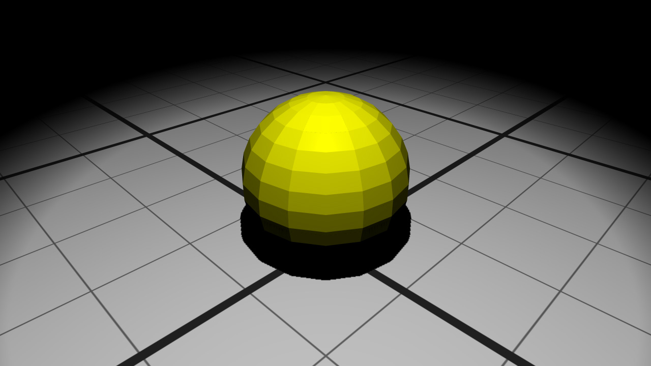
The facetted geometry
Let’s move to the shader programs in themselves now.
Vertex Shader
The vertex shader is used for two things here:
- Transforming vertex positions from object space to clip space
- Transferring the vertex positions and normals to the next pipeline stage
// Transform vertex from object space to clip space:
gl_Position = gl_ModelViewProjectionMatrix * gl_Vertex;

// Transform position from object space to world space
// and transfer it to the next stage:
// gl_TextureMatrix[1] contains the world matrix.
vec4 pos = gl_TextureMatrix[1] * gl_Vertex;
vertex_out.vPosition = pos.xyz;

// Transform normal from object space to world space
// and transfer it to the next stage:
vec4 nor = gl_TextureMatrixInverseTranspose[1] * vec4( gl_Normal.xyz, 1.0 );
vertex_out.vNormal = nor.xyz;
Geometry Shader
To facettize the geometry, this shader needs to redefine the vertex normals for each triangle of the geometry.
Its inputs are triangles and its outputs are triangle strips composed of 3 vertices (i.e. a single triangle):
layout( triangles ) in;
layout( triangle_strip, max_vertices = 3 ) out;
First we have to calculate the normal of the triangle:
// Compute the triangle normal from world space positions:
vec3 p0p1 = vertex_in[ 1 ].vPosition - vertex_in[ 0 ].vPosition;
vec3 p0p2 = vertex_in[ 2 ].vPosition - vertex_in[ 0 ].vPosition;

vec3 tri_nor = normalize( cross( p0p1, p0p2 ) );
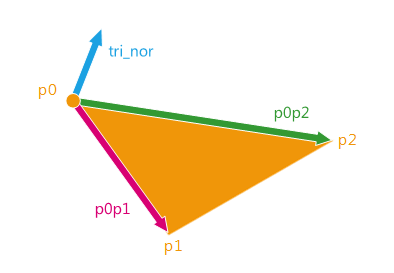
Calculating the normal of the triangle
Then we will create the three output vertices setting them the same triangle normal:
// Transmit the clip space position:
gl_Position = gl_in[ 0 ].gl_Position;

// Transmit the world space position and normal:
vertex_out.vPosition = vertex_in[ 0 ].vPosition;
vertex_out.vNormal = tri_nor;

EmitVertex();
The vertex positions do not change and are transmitted to the next stage of the pipeline as well as the new normals.
Note
Actually, as the normals are overwritten here, we did not have to handle the original ones through the vertex shader.
Pixel Shader
At the end of the pipeline, the pixel shader is a common phong reflection shader. It uses the transmitted positions and normals and handles diffuse and specular terms as well as shadows:
// Phong lighting:
vec3 light   = normalize( vec3( lightPos ) - vertex_in.vPosition );
vec3 normal  = normalize( vertex_in.vNormal );
vec3 eye     = normalize( vec3( eyePos ) - vertex_in.vPosition );
vec3 reflect = 2.0 * clamp( dot( normal, light ), 0.0, 1.0 ) * normal - light;

float diffuse = clamp( dot( light, normal ), 0.0, 1.0 );
float specular = pow( clamp( dot( reflect, eye ), 0.0, 1.0 ), 60.0 );
float shadow = texture2DRect( lightShadow, vec2( gl_FragCoord ) ).x;

gl_FragColor = objectColor * lightColor * ( diffuse + specular ) * shadow;
gl_FragColor.w = 1.0;
The variables like the light position, the light color, the object color or the eye position are parameters transmitted via RED::RenderShaderParameter.
// e. Some shader parameters:
RED::RenderShaderParameter lightPos( "lightPos", 0, RED::RenderShaderParameter::PSH );
lightPos.SetReference( RED::RenderShaderParameter::REF_LIGHT_POS_WCS );
RC_TEST( facetted.AddParameter( lightPos, RED_LS ) );

RED::RenderShaderParameter lightColor( "lightColor", 0, RED::RenderShaderParameter::PSH );
lightColor.SetReference( RED::RenderShaderParameter::REF_LIGHT_DIFCOL );
RC_TEST( facetted.AddParameter( lightColor, RED_LS ) );

RED::RenderShaderParameter objectColor( "objectColor", 0, RED::RenderShaderParameter::PSH );
objectColor.SetValue( g_sphere_color );
RC_TEST( facetted.AddParameter( objectColor, RED_LS ) );

RED::RenderShaderParameter eyePos( "eyePos", 0, RED::RenderShaderParameter::PSH );
eyePos.SetReference( RED::RenderShaderParameter::REF_EYE_POS_WCS );
RC_TEST( facetted.AddParameter( eyePos, RED_LS ) );

RED::RenderShaderParameter lightShadow( "lightShadow", 0, RED::RenderShaderParameter::PSH );
lightShadow.SetReference( RED::RenderShaderParameter::REF_LIGHT_SHADOW_IMAGE_TEX );
RC_TEST( facetted.AddParameter( lightShadow, RED_LS ) );
Exploded Shader
In a second part, we will start from the previous code and update the geometry shader to explode the geometry at runtime.
The new vertex normals will be used to also translate the vertices giving the following result:
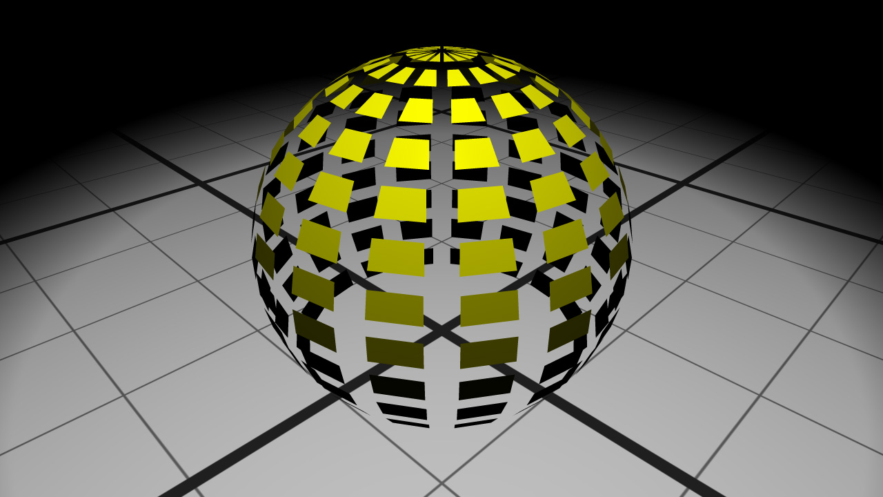
The exploded geometry
The vertex and pixel shaders do not change from the previous section.
The new geometry shader now outputs the new translated position:
// Translate the world space position:
vec3 pos = vertex_in[ 0 ].vPosition + tri_nor * explodingSize;

// Transmit the clip space position:
gl_Position = gl_ProjectionMatrix * gl_TextureMatrix[0] * vec4( pos, 1.0 );

// Transmit the world space position and normal:
vertex_out.vPosition = pos;
vertex_out.vNormal = tri_nor;

EmitVertex();
The input vertex data contains the vertex position in world space. We simply translate it along the triangle normal. The geometry shader vertex output must be in clip space. This is why we transform the position with the projection and view matrices.
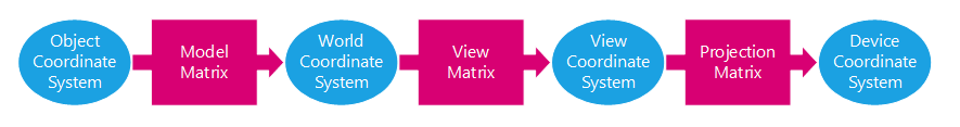
From object space to device space transformations stages
The translation length is transmitted to the shader via a RED::RenderShaderParameter :
RED::RenderShaderParameter explodingSize( "explodingSize", 0, RED::RenderShaderParameter::GSH );
explodingSize.SetValue( g_exploding_size );
RC_TEST( explode.AddParameter( explodingSize, RED_LS ) );
A RED::StateShader is also added at the beginning of the pass to disable the face culling (RED::StateShader::SetFaceCulling). Thus the back faces of the object could be seen through the exploded geometry.
Note
Because the material changes the vertex positions, the geometry shader program must also be added to all the shaders in the material. In our tutorial, we add it to the ambient shader in the prelit pass. The state shader disabling the face culling must also be added to the prelit pass.

