Hidden Lines Removal: A Real-Time Example
This tutorial starts from a simple CAD model and adds a real-time rendering of hidden edges to the display. This is done in real-time using the GPU. Hidden edges add an extra level of understanding to the model, as illustrated below:
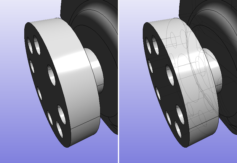
Before addition of hidden edges and after
Adding Backward Edges
Adding hidden edges is simple: just add another shading pass with a backward display setup and voila! This shading pass must be assembled by gathering a RED::StateShader and a RED::RenderShader. If we add it to the existing edge material, then our edges will be drawn twice (they’ll be drawn once for each rendering shader found).
Let’s detail the state shader configuration we need to be drawn if we’re hidden:
RED::StateShader ssh;
RC_TEST( ssh.SetDepthFunction( RED::StateShader::GREATER ) );
RC_TEST( ssh.SetBlendingMode( RED::StateShader::ADDITIVE ) );
RC_TEST( ssh.SetDepthTest( RED::StateShader::ON ) );
RC_TEST( ssh.SetLineStipple( true ) );
RC_TEST( ssh.SetLineStipplePattern( 1, (unsigned short)0x3333 ) );

RC_TEST( imatr->RegisterShader( ssh, iresmgr->GetState() ) );
RC_TEST( imatr->AddShaderToPass( ssh.GetID(), RED::MTL_POSTLIT, RED::LIST_LAST, RED::LayerSet::ALL_LAYERS, iresmgr->GetState() ) );
How does this work?
- First, we need to be rendered after geometries. This is why the
RED::StateShaderis set in theRED::MTL_POSTLITpass. The rendering shader will also need to be set in that pass. This ensures that all the shaders in theRED::MTL_PRELITandRED::MTL_LITpasses are processed first before we get processed too.- Then, we need to be drawn if…we are hidden, hence the call to
RED::StateShader::SetDepthFunction``( ``RED::StateShader::GREATER) and toRED::StateShader::SetDepthTest``( ``RED::StateShader::ON). That second call is needed because of the Default Pass Startup State Shader Configurations. These two calls will ensure that an edge will be rendered if its depth is greater than the actual contents of the depth buffer. This will make sure that we’re hidden to be displayed.
The remaining calls are to display edges with a dashed style and to fade them in the display. We’ll detail this later on. Now, from this, we’re good: we can have hidden edges added to the display, just by performing a modification of the original line material.
But…
Line Stipple Pattern Issues
Everything is fine until you want to see a nice stipple pattern applied on your edges (backward edges or not, this doesn’t matter here). The application of line stipple patterns require edges to be defined as a line strip. To understand this, we must get to how the hardware processes line data for the application of a stipple pattern:
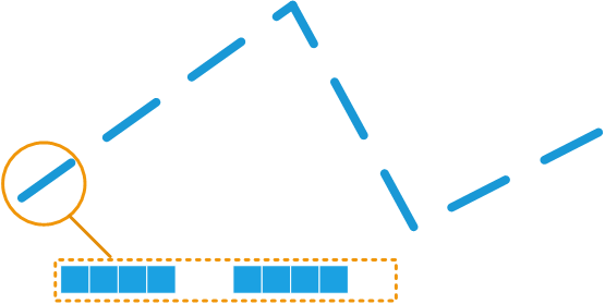
A stipple pattern applied to a strip
The hardware counts the number of pixels drawn - on screen - from the beginning of a strip and decides on shading this pixel or not, based on the specified pattern. This has two consequences:
- The pattern remains visible whatever the zoom level of the primitive. The pattern is drawn based on screen pixels, and not based on geometry.
- The length of the pattern is still correct at strip edges where the direction of the strip may change. Again, this is the number of pixels actually drawn on screen that matters and how they’re counted from the startup of the strip.
If we were to draw segments, then the hardware would restart the pixel counter for each segment drawn. In the case of segments, the graphic hardware has no idea on the connectivity of two segments, therefore, it can’t count pixels beyond each segment. Consequently, if we were to render the same lines as above with segments, we would get that:
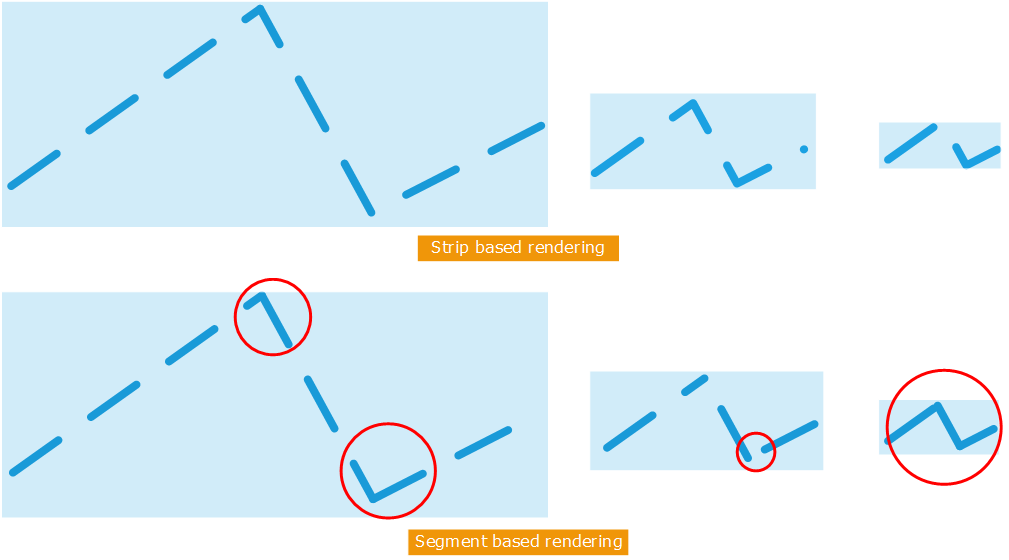
Comparison of strip and segment based stipple patterns
The stipple pattern is properly displayed in all circumstances if we use a strip. Otherwise, if we draw with segments when we zoom out, we tend either to see nothing (case of a stipple pattern with more holes than filled pixels) or a plain line (case of a stipple pattern with more filled pixels than holes). The red circles indicate problems.
So, how can this be solved?
Parametrization of Edges
HOOPS Luminate has an integrated edge reconstruction operator. This is the RED::ILineShape::Parametrize operator. It can be generally used after a RED::ILineShape::Collapse operation to ensure that the connectivity of all edges we have is correct.
RC_TEST( ilnewline->Collapse( 1e-5, iresmgr->GetState() ) );
RC_TEST( ilnewline->Parametrize( RED::MCL_TEX0, iresmgr->GetState() ) );
The parametrize operation changes the organization of edge data to make it become a unique big strip with parametric information stored on edges so that we can display them properly. The documentation of the RED::ILineShape::Parametrize method provides all details on this.
This require a special material, as stated in the method documentation. For the display of regular edges, the RED::IResourceManager::CreateParametrizationMaterial helper can be used, otherwise, the tutorial code provides the necessary shader to leverage the parametric information stored in the edges.
New Scene Graph
Consequently, we have to change our scene graph a bit: Due to the need for a new edge organization, we have created another edge shape for the storage and display of backward edges. We add this shape as another child under the parent of our original source shape.
RED::Object* parent;
const RED::Vector< RED::Object* >* parents;
RC_TEST( isline->GetParents( parents ) );
for( int i = 0; i < (int)parents->size(); i++ )
{
    parent = (*parents)[i];
    RED::ITransformShape* itparent = parent->As< RED::ITransformShape >();
    RC_TEST( itparent->AddChild( newline, RED_SHP_DAG_NO_UPDATE, iresmgr->GetState() ) );
}