Transform Shapes
The transform shape is a key shape in any scene graph, simply because this is the only shape that has a list of children shapes. Therefore, this is the node in the hierarchy of shapes used to define a scene for the rendering. A transform shape is created using the code detailed in the task here: Creating and Destroying Shapes, using the CID_REDTransformShape identifier.
In HOOPS Luminate, shapes are accessed using interfaces. The current implementation of the transform shape supports several interfaces:
| Interface | Description |
|---|---|
RED::ITransformShape |
Global shape API. Controls shape tree navigation and shape attributes. |
RED::IShape |
Global shape API. Controls shape tree navigation, shape attributes (material, bounding spheres, layersets…), culling callbacks. |
RED::IUserData |
User data API to store application custom data associated to a shape. |
RED::IChunkSaver |
Shape serialization interface. |
RED::IReferenceSolving |
Shape serialization interface. |
Setting Up a Scene Graph Hierarchy
As a design result, we have separated the scene graph navigation from the scene graph construction. The scene graph navigation API is found in the RED::IShape interface. This interface offers access to all navigation services (for example: RED::IShape::GetChildren or RED::IShape::GetParents) while it does not offer any scene graph construction services that are all located in the RED::ITransformShape API.
Therefore, the recursive parsing of a scene graph is quite easy, as the kind of shape being manipulated does not really matter:
RED_RC ParseChildren( RED::Object* shape )
{
  if( !shape )
    RC_TEST( RED_BAD_PARAM );

  int i, count;
  RED::Object* child;

  RED::IShape* ishape = shape->As< RED::IShape >();
  RC_TEST( ishape->GetChildrenCount( count ) );
  for( i = 0; i < count; i++ )
  {
    RC_TEST( ishape->GetChild( child, i ) );
    RC_TEST( ParseChildren( child ) );
  }

  return RED_OK;
}
Then, building a scene graph hierarchy is a task detailed below:
Adding or Removing Children from a Transform Shape
A shape hierarchy is built using a transform shape created using the CID_REDTransformShape. See Creating and Destroying Shapes. Then, the following code can be used to manipulate the list of children of a shape from the RED::ITransformShape interface:
// Creating a transform shape:
RED::Object* transform = RED::Factory::CreateInstance( CID_REDTransformShape );
if( !transform )
    RC_TEST( RED_ALLOC_FAILURE );

// Accessing the needed interface to manipulate the shape list of children:
RED::ITransformShape* itransform = transform->As< RED::ITransformShape >();

// Add a 'meshA' shape. Here we don't update our scene graph bounding spheres:
RC_TEST( itransform->AddChild( meshA, RED_SHP_DAG_NO_UPDATE, iresmgr->GetState() ) );

// Remove 'meshB' shape, and update the bounding spheres in the shape hierarchy to adapt to changes:
RC_TEST( itransform->RemoveChild( meshB, RED_SHP_DAG_UPDATE, iresmgr->GetState() ) );
Note that for performance reasons, RED::ITransformShape::AddChild does not prevent duplicate insertion of the same child twice or more. A given child should be added once. Adding the same child shape several times is an error that can cause unpredictible engine behaviors.
Setting Up a Transformation Matrix
The transformation matrix stored by the transform shape is used to position objects in the scene graph. The transformation matrix set is relative to the own shape coordinate system. This is illustrated in the tutorial here: Shapes Hierarchy.
From a pure programming standpoint, the matrix defined in the transform shape is set using RED::ITransformShape::SetMatrix. The matrix can be either NULL, indicating that there’s no extra transformation for the node in the scene graph, or it can be any 4x4 homogeneous transformation defined by a RED::Matrix object.
Usual transformation matrices in HOOPS Luminate are composed of translation, rotation and scale components, resulting in a block based matrix:
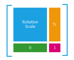
Usual TRS transformation matrices
Due to the fact that matrix operations are not commutative, the order of a transformation composition matters when dealing with matrices. Below are a few classic matrix composition examples that can be stored in a transform node as a resulting matrix, or that’ll be applied to shape geometries on collecting all transformation from the root of a scene graph down to the shape to visualize:
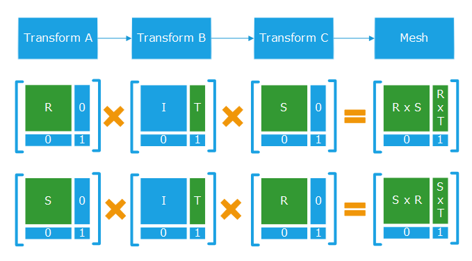
Combination of matrices applied to three transform and the final matrix applied to a mesh
Using Indirect Transformation Matrices
Indirect transformation matrices can be used in HOOPS Luminate and applied to scene graph transform shapes. Transformations with negative scaling can be used too. However, the application of a negative scaling or of any indirect matrix trnasformation on one geometry should flip the visible side of the polygons as illustrated below:
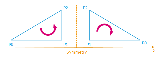
The application of an indirect transformation such as a symmetry cause a polygon heading change
In these configurations, HOOPS Luminate automatically reverts the polygon heading in the case of negative transformations. This is done at the hardware level (or by the ray-tracer) by changing the face culling of the considered shape polygons before rendering them. Face culling is a property accessible in the RED::StateShader configuration shader, and define which face of a polygon is visible, as a result of the polygon itself.
Please remind that normals don’t play any role in the determination of the visible face of a polygon. Normals are vertex attributes that are used for shading purposes, but they don’t interfere with the geometrical visibility of a triangle (P0,P1,P2) which results only of the direction pointed to by cross( P0P1, P0P2 ).
Using Non Conventional Transformations
Non conventional transformation matrices can be used in HOOPS Luminate transformation nodes. A good example of non conventional transformation matrix is the use of a perspective matrix as a node transformation. Using these matrices is supported by HOOPS Luminate, and geometries will be properly displayed on screen. However, shading calculations that are relying on camera parameters may appear wrong, as the relationship between the camera and the real model position may be non linear.
Transforming Normals using Differential Scaling Matrices
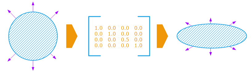
Differential scaling matrices are often used too. They cause a deformation of the geometry, for example by flattening it along the z axis as illustrated below:
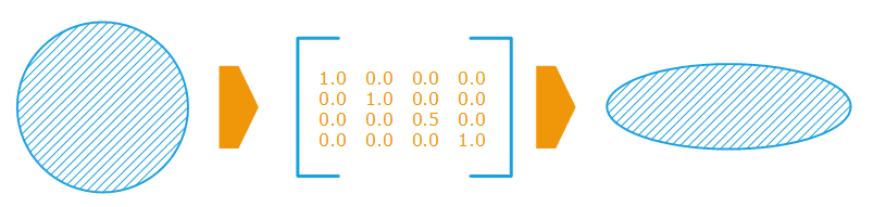
The effect of a differential scaling on the geometry
If we consider the normals in the transformation, these get wrong if we apply the raw transformation to them:
Differential scaling cause wrong geometrical normals after transform
Correct normals are retrieved by the application of the inverse scaling of the matrix to them. In our example, the z scale should be 2.0 instead of 0.5:

Apply an inverse scaling matrix to get correct normals
Therefore, when we have to apply a transformation to objects to get them back into view space for shading purposes, we do use the inverse transpose of the transformation matrix for normals. Indeed:
- The transposed matrix of a rotation matrix is equal to its inverse.
- The transposed matrix of a scaling matrix is equal to itself.
So, if we have a matrix M equal to the product of a rotation ‘R’ and a scaling ‘S’, then:
M = R * S
M.inverse = ( R * S ).inverse
M.inverse = S.inverse * R.inverse
M.inverse.transpose = ( S.inverse * R.inverse ).transpose
M.inverse.transpose = R.inverse.transpose * S.inverse.transpose
M.inverse.transpose = R * S.inverse
It happens that ‘M.inverse.transpose’ is the transformation we need to get back correct normals, whereas ‘M’ is to be used for the transformation of vertex positions.

