Building Basic Primitives
In this article, we’ll see how to create basic 3d primitives from scratch using HOOPS Luminate. With HOOPS Luminate, three main kinds of 3d primitives are available:
- Point Shapes
- Line Shapes
- Triangle Shapes
Each of the following sections will cover one of those. You’ll also see how to setup a perspective camera and assemble the whole thing together to render the data.
Building Shapes with HOOPS Luminate
Whatever the type of the shape you want to create, the process to follow is the same. First, you need to call the RED::Factory::CreateInstance method to perform the object instantiation:
RED::Object* point_shape = RED::Factory::CreateInstance( CID_REDPointShape );
if( point_shape == NULL )
    return RED_ALLOC_FAILURE;
Then, you have to request the needed interface from the object to start modifying it:
// Get the point shape interface from the newly created object.
RED::IPointShape* ipoint = point_shape->As< RED::IPointShape >();
How to Setup a Point Shape?
Using the interface to the shape, it’s easy to setup shape data. All the geometric shapes in HOOPS Luminate share the same internal structure made of 16 data channels (vertices, normals, texture coordinates…) and an extra indices array.
Those arrays must be filled by the caller and then set to the object using the various RED::IPointShape::SetArray methods. The array allocation can be made on the application side or directly by the engine itself. In our example, we use the second method:
// Start by allocating the point vertices array; this is accomplished by
// calling the SetArray method with a NULL pointer.
//
RC_TEST( ipoint->SetArray( RED::MCL_VERTEX, NULL, 500 * 500, 3, RED::MFT_FLOAT, iresmgr->GetState() ) );
By calling RED::IPointShape::SetArray with a NULL pointer and the final size of the array, the engine allocates the needed space by itself. Then, you can gain access to the allocated array by calling RED::IPointShape::GetArray:
float* vertices;
int size;
RED::MESH_FORMAT format;
RC_TEST( ipoint->GetVertexArray( (void*&)vertices, size, format, iresmgr->GetState() ) );
To setup a point mesh, we need to fill the vertices array which contains the raw list of point coordinates and the indices array (which in that case is a simple list of sequential indices from 0 to #points-1):
for( int p = 0; p < (500 * 500); ++p )
{
    float x = ( p % 500 ) - 250.f;
    float y = ( p / 500 ) - 250.f;
    float a = x * x + y * y;

    // Write the x, y and z coordinates of each vertex.
    vertices[3*p+0] = x;
    vertices[3*p+1] = y;
    vertices[3*p+2] = 10.f * sinf( a * RED_PI * 0.0001f );

    // Write the point index.
    indices[p] = p;
}
Here we are: we now have a fully defined basic point shape ready to be rendered.
Perspective Camera Creation
To visualize our shape, we need a valid camera to be created and defined. With HOOPS Luminate, you can create various kinds of cameras: orthographic, perspective or custom. Here, we’ll investigate how to create a perspective one.
As for any other object, we call the RED::Factory::CreateInstance method to instantiate the camera before getting back its interface:
RED::Object* camera = RED::Factory::CreateInstance( CID_REDViewpoint );
if( camera == NULL )
    return RED_ALLOC_FAILURE;

RED::IViewpoint* icamera = camera->As< RED::IViewpoint >();
The camera is located in (-200, -200, 50) and points to (0, 0, 0) with its vertical axis pointing along the z-axis:
RED::Vector3 eye( -200, -200, 50 );
RED::Vector3 sight, top, right;

sight = -eye;
sight.Normalize();
top = RED::Vector3::ZAXIS;
right = sight.Cross2( top );
top = right.Cross2( sight );

RED_RC rc = icamera->SetEye( eye, iresmgr->GetState() );
if( rc != RED_OK )
    return rc;

rc = icamera->SetViewingAxis( sight, top, right, iresmgr->GetState() );
if( rc != RED_OK )
    return rc;

rc = icamera->SetFrustumPerspective( RED_PI / 4.f, 1.f, iresmgr->GetState() );
if( rc != RED_OK )
    return rc;

rc = icamera->SetNearFar( 0.1f, 10000.f, iresmgr->GetState() );
if( rc != RED_OK )
    return rc;
We also tune the near and far clipping planes to something quite generic (0.1, 10000.0).
The latest step before visualizing something is to add the shape to the camera by calling RED::IViewpoint::AddShape.
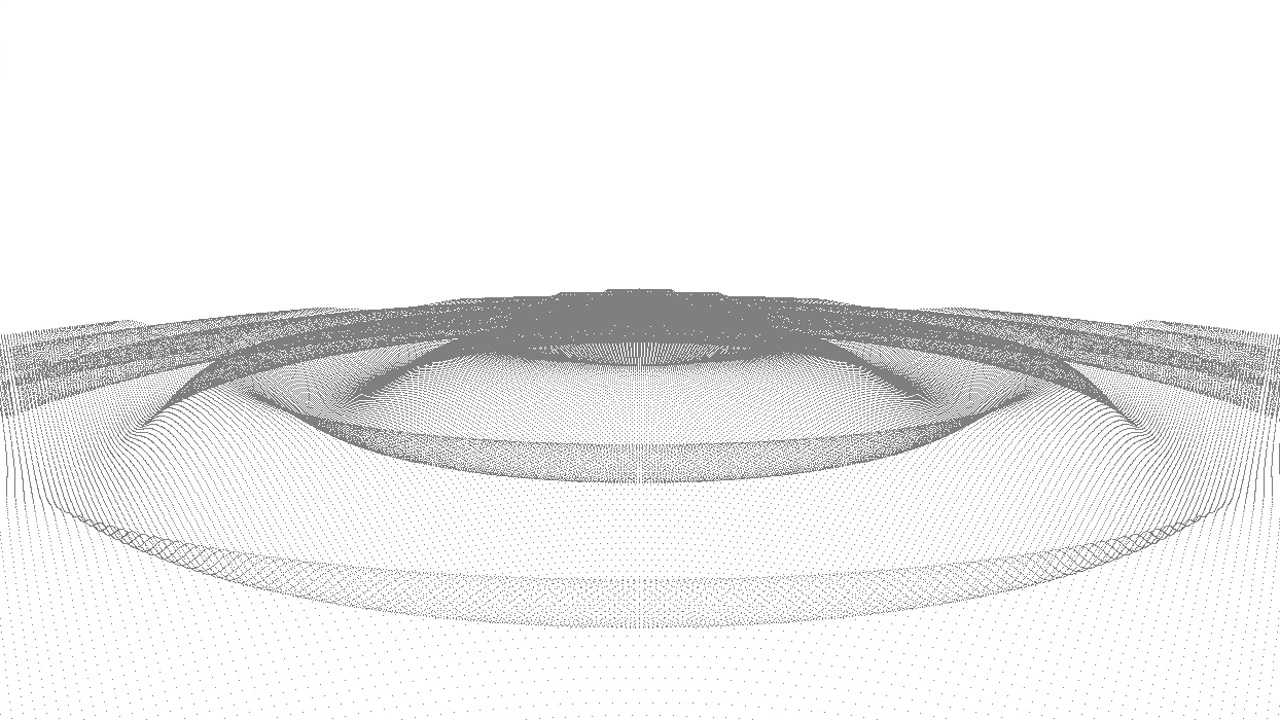
Our point shape
Building Line Shapes
Building a line shape is very similar to building a point one. The main difference arises when it comes to set the line indices. The line may be either segment or strip-based.
In the first case, each pair of indices describes the start and end point of a segment. Hence, a line shape with 256 segments contains 512 indices. In the second case, each index is a point along the strip. A strip of length 257 will be rendered as 256 segments. Each kind of line shape is demonstrated in the following code:
Segment-Base Line Shape
int* segments;
int segments_count;
RC_TEST( iline->AddSegments( NULL, 256, iresmgr->GetState() ) );

// Fill the line indices array.
RC_TEST( iline->GetSegments( segments, segments_count, iresmgr->GetState() ) );

for( int i = 0; i < segments_count; ++i )
{
    segments[2*i+0] = i;
    segments[2*i+1] = ( i + 1 ) % 256;
}
Strip-Based Line Shape
int strip_length = 257;
int* strip = (int*)rmalloc( sizeof( int ) * strip_length );
int strips_count = 1;

// Fill the line indices array.
for( int i = 0; i < strip_length; ++i )
    strip[i] = i % 256;

RC_TEST( iline->AddStrips( strip, &strip_length, strips_count, iresmgr->GetState() ) );
Both shapes share the same vertices array of length 256 and render the same:
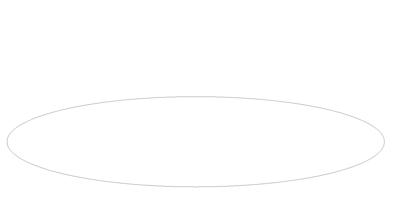
The line shape
Building Triangle Shapes
Triangle shapes are a little bit more difficult to build than others because they need some additional information to be set. Amongst available channels, we decided to fill normals and texture coordinates along with vertices in this example:
// Create the triangle shape.
RED::Object* triangle_shape = RED::Factory::CreateInstance( CID_REDMeshShape );
if( triangle_shape == NULL )
    return RED_ALLOC_FAILURE;

RED::IMeshShape* imesh = triangle_shape->As< RED::IMeshShape >();

int nb_rdiv = 32;
int nb_hdiv = 16;
int nb_ver = nb_rdiv * nb_hdiv;
int nb_tri = 2 * ( nb_hdiv - 1 ) * nb_rdiv;

// Allocate the memory of each array...
RC_TEST( imesh->SetArray( RED::MCL_VERTEX, NULL, nb_ver, 3, RED::MFT_FLOAT, iresmgr->GetState() ) );
RC_TEST( imesh->SetArray( RED::MCL_NORMAL, NULL, nb_ver, 3, RED::MFT_FLOAT, iresmgr->GetState() ) );
RC_TEST( imesh->SetArray( RED::MCL_TEX0, NULL, nb_ver, 2, RED::MFT_FLOAT, iresmgr->GetState() ) );
RC_TEST( imesh->AddTriangles( NULL, nb_tri, iresmgr->GetState() ) );
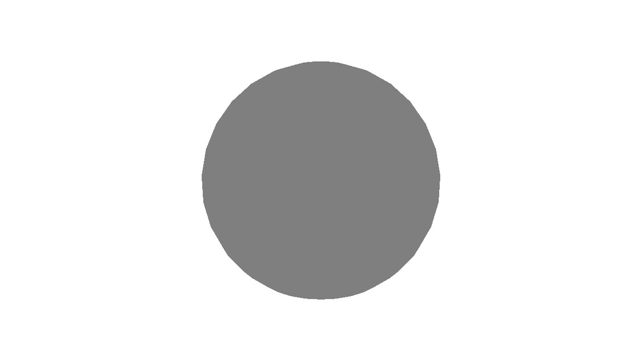
The triangle shape
Normals are needed as soon as we need to shade the geometry as it will give information about how the surfaces are oriented regarding to the incoming light in the scene. Texture coordinates are useful to apply texture images to the triangles for better look.

