Life Cycle of HOOPS Luminate Objects
There are two distinct mechanisms in HOOPS Luminate to manage the life and memory of objects that are created by the application. These mechanisms differ depending on how the object was initially created:
- Objects created using
RED::Factory::CreateInstanceare following a Graph Based Destruction Method, as seen below.- Objects created directly using the
RED::IResourceManagerinterface are following a Shared Resource Destruction Method as seen below.
It’s also very important to know that in HOOPS Luminate, destruction orders are not immediate. Except for images - which are mostly synchronous objects - all destruction orders of objects that are using transactions are postponed until the transaction is closed using RED::IResourceManager::EndState.
Graph Based Destruction Method
The graph based destruction method applies to:
- The resource manager
- Windows
- Viewpoints
- Viewpoint render lists
- Shapes
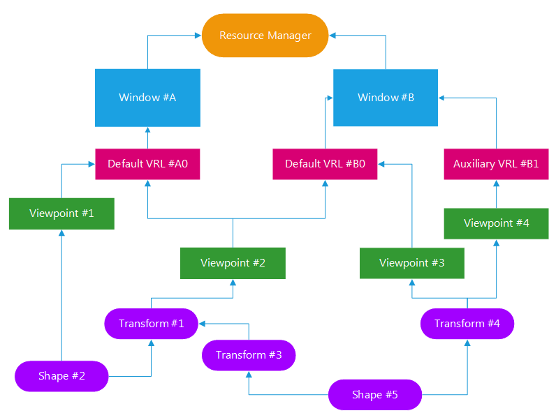
An example application object graph
The one and unique rule about object destruction here is that the destruction of an object will cause the destruction of all children objects in its proprietary sub-graph. This means that any object that is destroyed will destroy all its children objects that are not linked elsewhere, ‘elsewhere’ being not destroyed. Let’s see how this applies to the schema above:
- If the resource manager is destroyed, everything is destroyed: using a single call, all HOOPS Luminate data gets released.
- If window #A or #B is being released, here’s what remains alive:
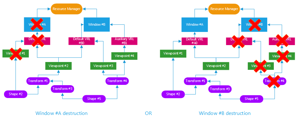
The fact that ‘viewpoint #2’ is linked to both windows prevent it to be destroyed (of course if we consider one of the two destruction orders. If both windows are destroyed at the same time, everything is destroyed). Consequently shapes below ‘viewpoint #2’ are not destroyed.
- If destruction occurs at the viewpoint level, for instance deleting ‘viewpoint #2’ and ‘viewpoint #4’, here’s what remains alive:
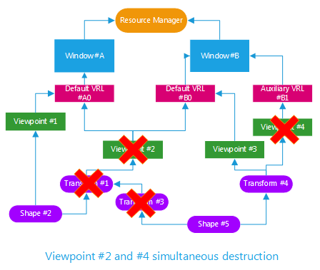
‘Shape #2’ was linked to both viewpoints numbers 1 and 2, so it survives. Similarly, the destruction order of ‘viewpoint #4’ does not propagate further down, because ‘transform #4’ is linked to ‘viewpoint #3’ which survives the operation.
The Data Release Timer Option
This is a special engine option, called RED::OPTIONS_DATA_RELEASE_TIMER. This option controls the life cycle of internal GPU buffers used by the engine. It may be helpful to change its value in the case of multiple graphics intensive windows used in the application.

