Improving CAD Graphics
Many CAD applications whose primary purpose is the definition of parts and assemblies have a limited amount of parameters available regarding photo-realistic graphics. Therefore, increasing the quality of the calculated images - either for high quality real-time rendering needs or photo-realistic needs - may be somehow difficult, due to the fact that we simply miss the requested informations.
To follow the guidelines depicted in the Rendering Photo-Realistic Images for instances, one application will need a lot of parameters: it’ll require the setup of lights, the definition of an environment, definition of materials and also some rendering parameters. Many pure industrial CAD application simply don’t have that level of information available.
Therefore, how can we still improve the visual quality of CAD assemblies that have no graphic setup at all? This is the purpose of this book to provide one possible answer to this problem.
So, we’ll start from a simple CAD assembly. This is an engine model, for which we have:
- A CAD assembly, with parts and materials set on parts.
- One color information for each material.
As we can see in the image below, this is not a lot:
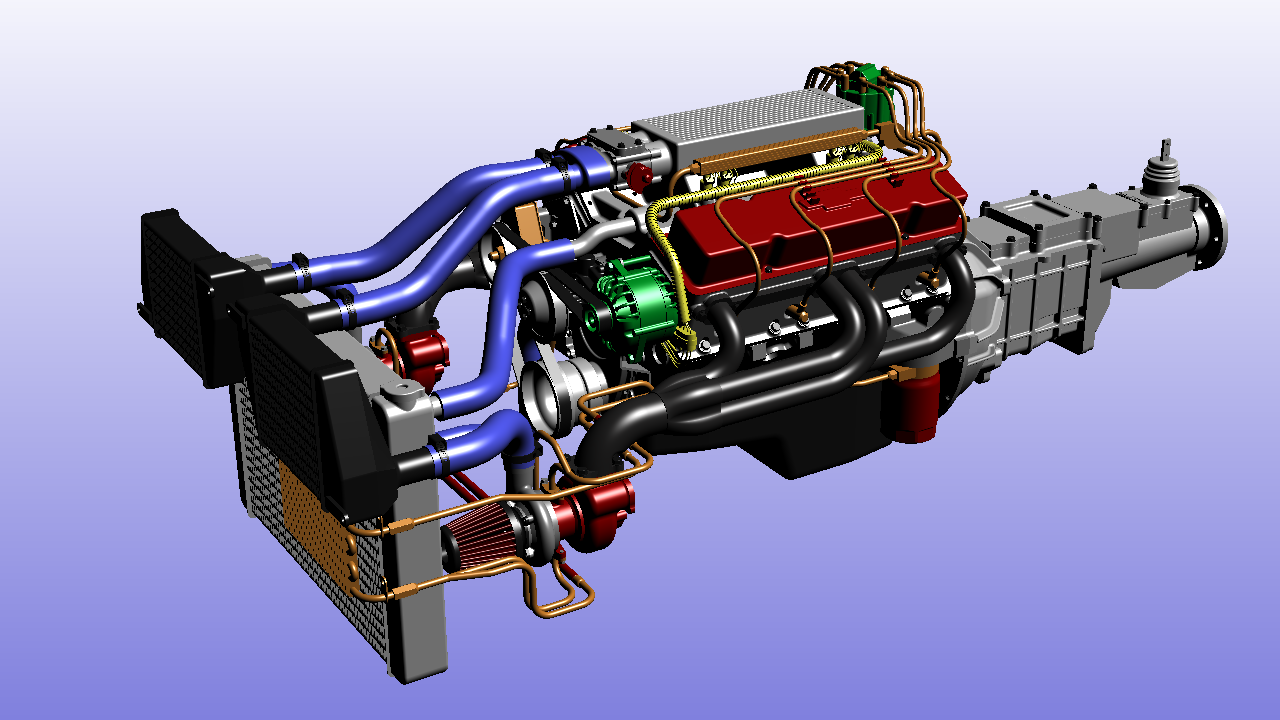
The startup assembly with one color for each small group of parts
We’ll work from this information, and we’ll reach the quality below:
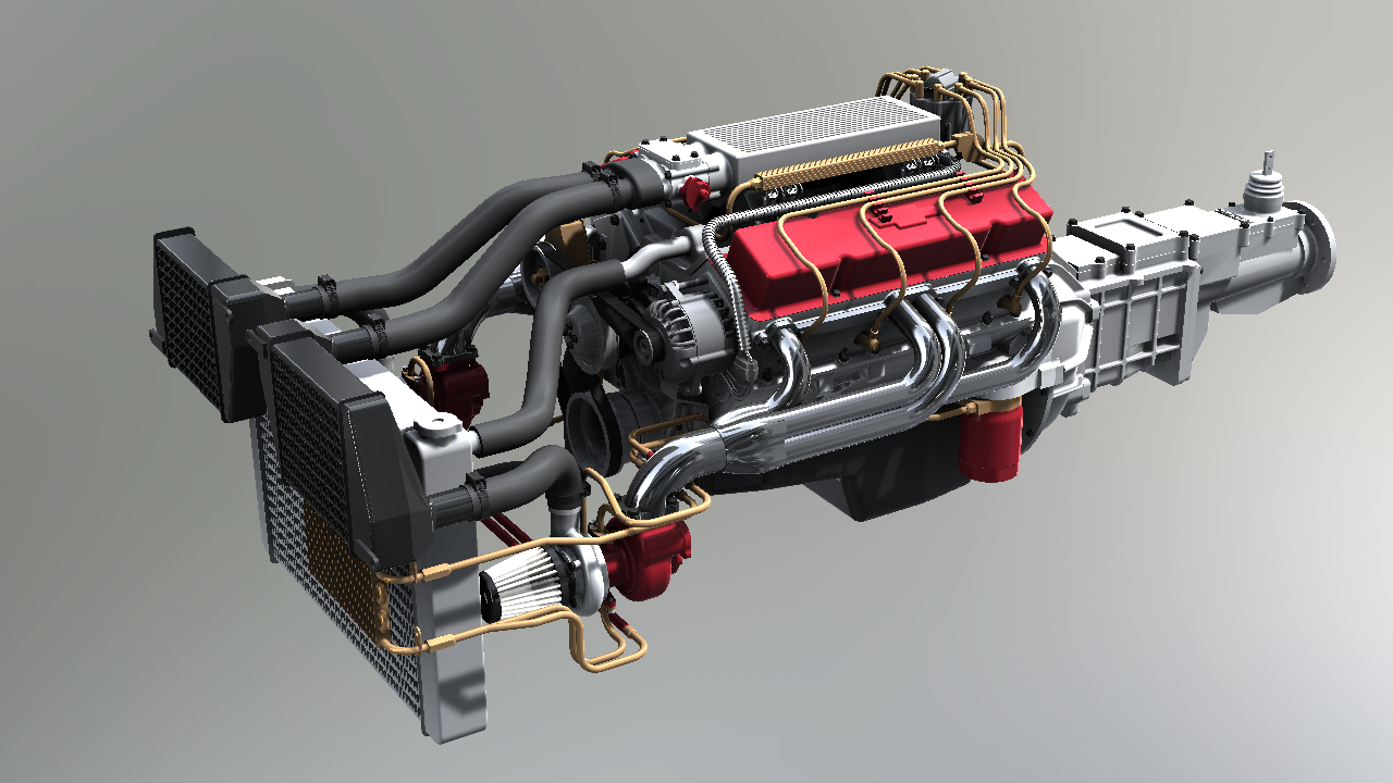
The final assembly rendered in real-time
We’ll remain real-time in all operations: In that specific example, the source model renders in less than 1 millisecond on any desktop computer, and it’ll render in roughly 3 milliseconds after the processing operation. So even on low end graphics, all the changes described in this book, applied to middle sizes assemblies of a few millions triangles, will continue to produce real-time graphics.
Overview of Changes
To reach the final quality level, we’ll combine several techniques available in HOOPS Luminate. We’ll do some pre-processing on the source model and we’ll use a custom scene setup to enhance the visual quality of our assembly. Basically our technique relies on a sunlight + skylight lighting setup with environmental mapping, on shadow mapping, on ambient occlusion, and on a Fresnel based reflectance model. All this is gathered into one single pass shader to keep optimal performances. Then, the rendering occurs in a HDR rendering pipeline allowing for changes in tone-mapping, in real-time.
- Sourcing Informations: As an early step, we’ll need to gather some extra informations from our assembly. Among the informations we’ll need we’ll look forward to apply a kind of material mapping between part colors and the materials they represent.
- Setup a Sun Shadowing Workflow: We’ll setup an offline mechanism to calculate shadows from the sun, on demand.
- Setup Environment Maps: We’ll setup different environment maps and skylight background maps for the simulation of different material glossiness settings, and for the background of our scene.
- Computing Ambient Occlusion: We’ll then compute a per-vertex ambient occlusion layer, stored as extra vertex channel informations. This will modulate the skylight contribution and environmental mapping.
- Assembling New Materials: We’ll continue with the setup of materials collecting all informations together and rendering them in one single pass.
- HDR Rendering Pipeline: And as a final step, we’ll setup our background, in a HDR pipeline and apply a simple tone-mapping operator to our model.
How to Use the CAD Graphics Builder
The HOOPS Luminate tutorial associated to the book packages a simple class: this is the REDCADGraphicsBuilder. This class should be easy to extract from the tutorial and to copy in any other HOOPS Luminate based application; Some cleanup must occur: All references to the RC_TEST macro should be replaced by another RED_RC testing macro, or RC_TEST should be redefined (the corresponding REDUITools.h include should be removed). Then, all references to the progress bar of the RFK tutorial framework should be removed too.
The REDCADGraphicsBuilder offers a base sandbox to play with different visual styles in real-time that generally work well with CAD assemblies.

