Software Display Performances
As for hardware display, we have a number of levers to activate to optimize the software display performances of a given scene in HOOPS Luminate. Software rendering behaves differently from hardware rendering, so our action means are different.
Geometry Does Not Matter That Much
In ray-tracing, the amount of geometry does not affect rendering performances as it does for hardware rendering. Using the GPU, the time taken by the processing of one single rendering pass is linearly proportional to the amount of data being rendered. In software ray-tracing, this is not true. Generally speaking, the increase in time is logarithmically increasing with the amount of data to draw, which makes extra data less and less costly to process.
Furthermore, in many configurations, if for instance there’s an occluding wall in front of the camera, then nothing else but the wall will be drawn, as rays won’t get through that wall. Using the GPU, objects that are behind the wall will be rendered anyway (unless there’s an occlusion culling algorithm available, but which is generally not efficient in the general case). Hidden objects will probably not be shaded, but they’ll have been processed anyway.
However, extra data with complex materials - such as refractive materials with glossy refractions - may have a significant cost to process due to the fact that rays can be trapped and bounce endlessly into these objects.
So material properties may affect rendering performances a lot more than geometry itself, and we’ll focus more on setting up proper materials than changing geometries.
Single Sided or Double Sided Geometries Make No Difference
Unlike for GPU based rendering for which setting dual sided materials does matter, software rendering don’t cares of the polygon facing. Performances are identical with single sided polygons and double sided polygons. This is due to the nature of the ray vs. triangle intersection process, that does the calculation. This method can be for example based on Möller-Trumbore algorithm which checks both sides of the triangle with almost the same code.
Too Much Energy Kill Performances
Effect of this are detailed here: Setup Materials under the section A Word on Color Saturation. If a material emits too much energy and does not preserve energy, this can have a bad visual effect and this can slow down the rendering. The energy preservation rule states that a material should have a sum of diffusion + reflection + transmission terms lower than or equal to 1.0.
If a material does not enforce this rule (for example if it’s a white material with a white reflective color at the same time), then this material will ‘create’ energy, and ray-tracing calculations will have an increasing amount of energy to consider each time the material is involved in the rendering.
So as a general rule, all materials energy should follow an energy preservation rule. The realistic material always preserve energy, as seen in the doc Using Built-in HOOPS Luminate Materials.
Light Cutoff Option
The RED::OPTIONS_LIGHT_CUTOFF influences the effect area of a light that has an attenuation. Skylights, ambient lights, directional lights or other lights that have no decay equation are not influenced by this option. However, all lights that do have a decay in intensity are influenced by this option.
As detailed in the option documentation, the value of this option is empirical: it’s an absolute lighting intensity below which the contribution of a given light to a shaded point is ignored. This option enables the engine to calculate an area of effect for each light. Without this cutoff value, any light with a decay illuminates infinitely far away (the 1/d*d equation never reaches zero, or the solid angle of the light seen from the shaded point is not zero) while with a cutoff value, HOOPS Luminate can figure out a maximal effect area for a light that has a decay.
This option has a visual influence on the result when set too high, as illustrated below:
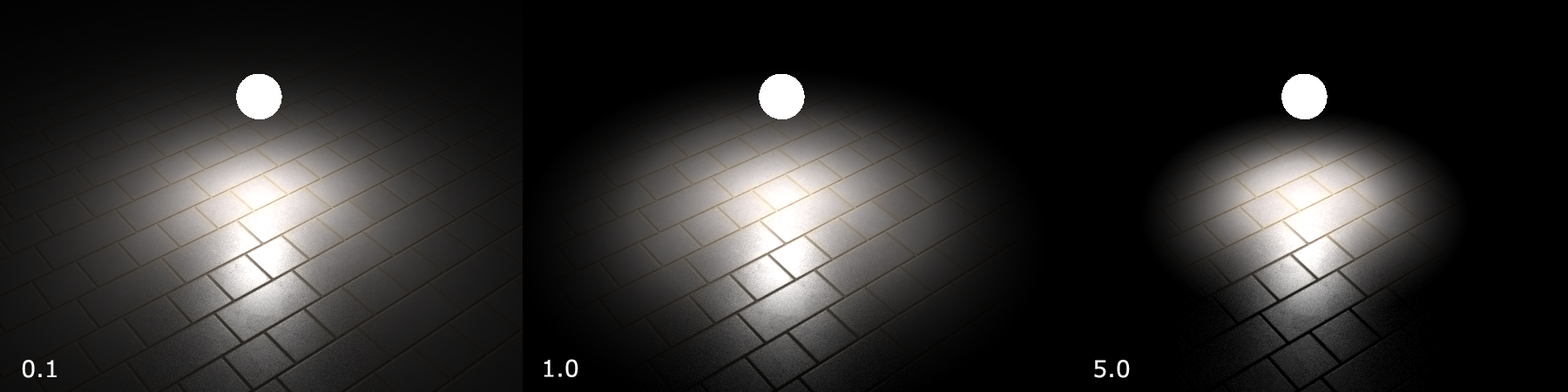
Effect of increasing the light cutoff on the shading produced by a light
In an environment with many lights, using this option can result in a great increase of the display performance with no visible effect on the resulting image. In the scene above, the value for which the cutoff starts to have a visible effect is greater than 1.0 while the default cutoff is set to 0.001. So there’s a margin for setting this value high enough to get a performance boost while having no visual effect on the image.
Ray Cutoff Option
The RED::OPTIONS_RAY_CUTOFF defines the minimal energy that a ray must have to be considered any further in the image propagation. As for the light cutoff option detailed above, the value of this option is empirical. It’s an absolute intensity propagated by the ray below which the path followed by that ray is being cut. This is illustrated below for different values of that option:
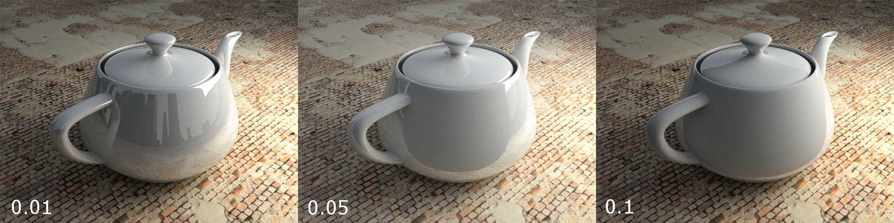
Effect of increasing the ray cutoff on visible reflections
Disabling this option (e.g. setting the ray cutoff value to 0.0) has a very bad effect on visual performance, while the image generally remain identical as with the default 0.01 value. We can see in the image above that a Fresnel based reflective teapot has weaker reflections when the reflection ray is facing the camera. Consequently the first cut areas in the image when we increase the ray cutoff value are reflections bouncing toward the camera.
Number of Rendering Threads
Ray-tracing algorithms do work well in parallel, so the more the number of threads used, the faster the rendering. Still, please find some details on how HOOPS Luminate behaves in software rendering: By default on starting a software rendering using one of the RED::IWindow::FrameTracing methods, HOOPS Luminate will launch a number of calculation threads equal to the number of CPU cores found on the computer, minus one (we have the calling thread too). So in total, the application should run a number of threads equal to the number of available CPU cores.
All threads participate to the image calculation. The main thread will return from the rendering method every ‘x’ milliseconds, where ‘x’ is the feedback interval specified to the RED::IWindow::FrameTracing method. So for ‘x’ milliseconds, the main thread will also participate to the calculation, then it’ll stop and return to the caller. On re-entering the method, calculations of the main thread will resume.
The number of threads can be reduced by changing RED::OPTIONS_RAY_MAX_THREADS.
Rendering Options
The Setup the Rendering page is a must have to read to setup ray-tracing options for a rendering. Increasing option values will have an influence on the rendering time as well as on the resulting quality.
The two most sensitive options here are the RED::OPTIONS_RAY_LIGHTS_SAMPLING_RATE and the RED::OPTIONS_RAY_GLOSSY_SAMPLING_RATE: increasing these rates will have a stong effect on the rendering time and on the resulting quality accordingly. Using low rates will produce noisy images.
Assuming that the quality of the Global Illumination is high enough, then the RED::OPTIONS_RAY_GI_FOR_LIGHTING and RED::OPTIONS_RAY_GI_FOR_GLOSSINESS values can help speeding up the rendering.
Changing the global depth of ray-tracing options may have an effect on rendering times too, but unless the scene contains a lot of refractive glasses, modifying the ray-tracing depth is less significant than changing other options.
Finally, the RED::OPTIONS_RAY_GI_CACHE_PRECISE option value increases the GI quality dynamically, but this has a cost too.

