Shapes Hierarchy
Introduction
HOOPS Luminate features a scene graph (Direct Acyclic Graph) which permits to build complex hierarchies of shapes and transforms. We’ll here show how one can setup a minimal robot arm using basic primitives.
Description
The robot arm is made of four cylinder primitives: one for the base and three for the arm. A spot light is added at the top of the third arm cylinder. The purpose is to freely move each arm part under some constraints. The base can only be translated over the plane or rotated along the z-axis. Each arm cylinder can only be rotated around the x-axis of a local system located at the bottom of each cylinder.
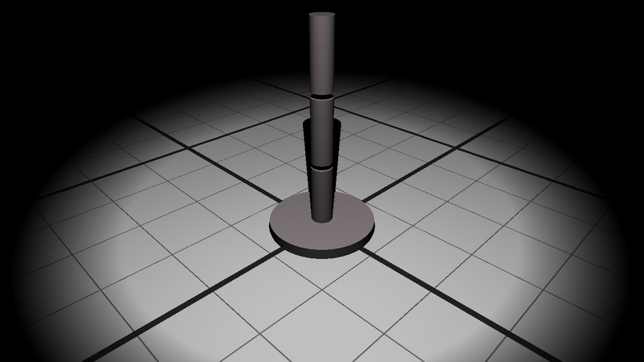
The initial robot arm model made of a base and three arm cylinders.
To apply natural constraints to each arm segment, we decide to build a hierarchy of shapes:
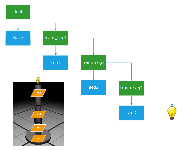
The RED scene graph of our simplistic robot arm: transform shapes are in green and mesh shapes are in blue.
The movement of each segment is relative to its parent and guarantees to always preserve the overall arm shape at no extra cost.
To build a hierarchy of shapes using HOOPS Luminate you need at least two kind of shapes: the RED::ITransformaShape that will handle transformation matrices and the RED::IMeshShape for the geometries themselves. Here is an example of the creation of the first robot arm segment:
// Seg1 primitive:
// ---------------
RED::Object* seg1 = RED::Factory::CreateInstance( CID_REDMeshShape );
if( seg1 == NULL )
    return RED_ALLOC_FAILURE;

seg1->SetID( "seg1" );

RED::IMeshShape* iseg1 = seg1->As< RED::IMeshShape >();
RC_TEST( iseg1->Cylinder( RED::Vector3( 0.f, 0.f, 0.f ), 2.f, 6.f, 64, iresmgr->GetState() ) );

// Put the seg1 primitive centered at the top of the base primitive.
RED::Matrix mat_seg1;
mat_seg1.Translate( RED::Vector3( 0.f, 0.f, 7.f ) );

RED::Object* trans_seg1 = RED::Factory::CreateInstance( CID_REDTransformShape );
if( trans_seg1 == NULL )
    return RED_ALLOC_FAILURE;

// Each new segment is declared as the child of the previous primitive. This actually determines
// our hierarchy of shapes and lets us later apply custom transformation to each while preserving
// our model constraints.
RED::ITransformShape* itrans = trans_seg1->As< RED::ITransformShape >();
RC_TEST( itrans->SetMatrix( &mat_seg1, iresmgr->GetState() ) );
RC_TEST( itrans->AddChild( seg1, RED_SHP_DAG_NO_UPDATE, iresmgr->GetState() ) );
The same goes for each robot arm segment.
To handle user interactions, we add a callback on mouse events. As soon as the user clicks over a shape of the robot arm, it becomes the picked shape. As long as the mouse button is not released, mouse cursor movements are translated into shape matrix transformations:
if( ( dx != 0 ) || ( dy != 0 ) )
{
// Get the transformation matrix of the picked primitive.
RED::Object* parent;
RC_TEST( primitive_shape->As< RED::IShape >()->GetParent( parent, 0 ) );

RED::ITransformShape* itrans = parent->As< RED::ITransformShape >();
if( itrans )
{
        RED::Matrix* mat;
        RC_TEST( itrans->GetMatrix( mat, iresmgr->GetState() ) );

        if( primitive_picked > 0 )
        {
            RED::Matrix rot;
            rot.RotationAxisMatrix( RED::Vector3( 0.f, 0.f, -6.f ), RED::Vector3::XAXIS, -dy * 0.1f );
            *mat *= rot;
        }
        else
        {
            if( event._mouse_right )
            {
                RED::Matrix rot;
                rot.RotationAxisMatrix( RED::Vector3( 0.f, 0.f, 0.f ), RED::Vector3::ZAXIS, dx * 0.1f );
                *mat *= rot;
            }
            else
            {
                RED::Vector3 dir_y( 1.f, 1.f, 0.f );
                RED::Vector3 dir_x( -1.f, 1.f, 0.f );
                mat->Translate( dir_x * dx * 0.15f + dir_y * dy * 0.15f );
            }
        }

        RC_TEST( itrans->SetMatrix( mat, iresmgr->GetState() ) );
        RC_TEST( app::Invalidate() );
    }
}
Depending on the type of the picked primitive (base or arm segment), different transformation matrices are allowed: the base can be translated or rotated along the z-axis (second case in the code above) while the arm segments can only be rotated around one axis (first case in the code above). The matrix derived from the user interactions is then concatenated to the original shape matrix through multiplication and applied back to the shape.

