Viewpoints
The viewpoint is the HOOPS Luminate camera. Viewpoint creation and basic operation is detailed just below. Of course, to be used, the viewpoint must be added to a RED::IViewpointRenderList, or added to the default VRL using the RED::IWindow::InsertViewpoint helper. In the HOOPS Luminate documentation we’ll either use the word ‘viewpoint’ or ‘camera’ to refer to HOOPS Luminate viewpoints.
Creating a Viewpoint and Visualizing Shapes
// Create a viewpoint directly, using the RED::Factory:
RED::Object* viewpoint = RED::Factory::CreateInstance( CID_REDViewpoint );
if( !viewpoint )
    RC_TEST( RED_ALLOC_FAILURE );

// Add shapes to visualize ('iresmgr' is our RED::IResourceManager interface, 'shape' is a RED::Object shape):
RED::IViewpoint* iviewpoint = viewpoint->As< RED::IViewpoint >();
RC_TEST( iviewpoint->AddShape( shape, iresmgr->GetState() ) );
The viewpoint is created directly from the RED::Factory. Shapes can be added to it simply using RED::IViewpoint::AddShape. Please note that performing this operation is similar to adding the shape to the scene graph root instead:
// Same operation, but accessing the scene graph root first:
RED::Object* root;
RC_TEST( iviewpoint->GetRootShape( root ) );
RED::ITransformShape* itroot = root->As< RED::ITransformShape >();
RC_TEST( itroot->AddChild( shape, RED_SHP_DAG_NO_UPDATE, iresmgr->GetState() ) );
A viewpoint always own a scene graph root. The scene graph structure that is visualized by a viewpoint is attached to its root. The RED::IViewpoint::AddShape and RED::IViewpoint::RemoveShape methods are convenient helpers to manage the scene graph structure. More advanced functions on the scene graph can be gained by accessing the root shape directly.
The base axis system of a camera is manipulated and accessed using:
RED::IViewpoint::SetEye,RED::IViewpoint::SetSight,RED::IViewpoint::SetTop,RED::IViewpoint::SetRightfor the main three camera axis, and the corresponding “Get” methods.RED::IViewpoint::GetNearFarto access the viewpoint’s near and far clip distances.
Other methods can be used to setup the viewpoint’s matrix as a whole, such as:
RED::IViewpoint::SetViewingAxisorRED::IViewpoint::SetViewingMatrix.
This chapter covers a number of different topics, among which:
- The description of all HOOPS Luminate supported projection models. All of them are reviewed down this page: Perspective Camera; Orthographic Camera, and Custom Camera.
- All the details on the HOOPS Luminate matrix transformation pipeline can be found there: Matrix Transforms in a Cluster. References that are familiar to OpenGL programmers are provided there.
Setting Up a Simple Camera
The setup of a viewpoint requires a few steps, once it has been created:
- Setup the viewpoint axis system: this includes the viewpoint sight, top, right vectors and the viewpoint’s eye position.
- Setup the viewpoint projection type we’re going to use. For basic viewpoints, this is
RED::VPT_PERSPECTIVEandRED::VPT_PARALLEL(we ignore custom camera projection models in this simple task);- Setup a near / far clip distances. This is a mandatory step to make sure that our viewing frustum is well defined.
And that’s it! The corresponding code is detailed below:
// create and access our viewpoint's interface:
RED::Object* viewpoint = RED::Factory::CreateInstance( CID_REDViewpoint );
if( !viewpoint )
    RC_TEST( RED_ALLOC_FAILURE );

RED::IViewpoint* iviewpoint = viewpoint->As< RED::IViewpoint >();

// 1. Setup our viewpoint axis system: Define where we want to look at. This is 'target', and the direction
//    from which we look at our target. This is 'sight'. We look at our target from a 'distance':
RED::Vector3 target( 1000.0, 300.0, 0.0 );
RED::Vector3 sight( -1.0, -1.0, -1.0 );
sight.Normalize();
double distance = 500.0;

RED::Vector3 eye, top, right;

// Calculate the eye position:
eye = target - sight * distance;

// Keep the head up (along the z axis), and compute the missing axis. We must ensure that our axis system
// forms an orthographic basis (e.g. each axis is perpendicular to others):
top = RED::Vector3( 0.0, 0.0, 1.0 );
right = sight.Cross2( top );
top = right.Cross2( sight );

RC_TEST( iviewpoint->SetEye( eye, iresmgr->GetState() ) );
RC_TEST( iviewpoint->SetViewingAxis( sight, top, right, iresmgr->GetState() ) );

// 2. Let's define a perspective projection for instance, assuming we're displaying into a 1920 x 1080 pixels window:
RC_TEST( iviewpoint->SetFrustumPerspective( RED_PI / 4.0f, 1080.0 / 1920.0, iresmgr->GetState() ) );

// 3. And finally set the near / far clip distances to complete our camera definition:
RC_TEST( iviewpoint->SetNearFar( 1.0, 10000.0, iresmgr->GetState() ) );
Applying a Layerset
Layersets are visibility masks. RED::LayerSet objects are detailed in the doc Shape Attributes in a Scene Graph under the section Layersets. There are two main usages for layersets:
- Visibility filtering. Layersets are used to discard objects from the visibility, as pointed out by the task “Change a Shape Visibility using Layersets”.
- Material configuration. Shaders in materials are set for specific layersets configurations (see Material Layersets).
All the layerset configuration system starts by the specification of the RED::LayerSet instance which is set at the camera level. Changing this layerset can affect the entire visibility of the scene graph. Call RED::IViewpoint::ApplyLayerSet to change the RED::LayerSet instance used for the visualization of the entire scene graph linked “under” the viewpoint.
Sharing a Viewpoint Among Windows and VRLs
There’s no restriction on sharing a viewpoint among different VRLs. The same viewpoint can be added to different VRLs for display. This is rarely used feature, that can be leveraged for instance to display the same scene with different rendering options, or to use different backgrounds or other VRL level informations for the same dataset.
Defining a Viewpoint’s Viewport
The viewport region in which a viewpoint will be rendered is defined at the RED::IViewpointRenderList level. A viewpoint gets inserted into a window using RED::IViewpointRenderList::InsertViewpoint. This method defines the exact area that’ll be covered by the viewpoint in the window rendering area. See also Anchoring Viewpoints in a Window.
Viewpoint Level Material Parameters
This is an important feature of the viewpoint. It has the capability to hold a set of RED::RenderShaderParameter objects, that can be assigned to IDs. Materials in scene graphs can then point to these parameters that are identified by their IDs. Therefore, the same material used by a shape that is viewed by two different cameras can have different values for the same material parameters.
All the details can be found in the documentation of the RED::IViewpoint::AddRenderShaderParameter method.
Perspective Camera
The RED::IViewpoint interface implements the pinhole perspective camera projection model:
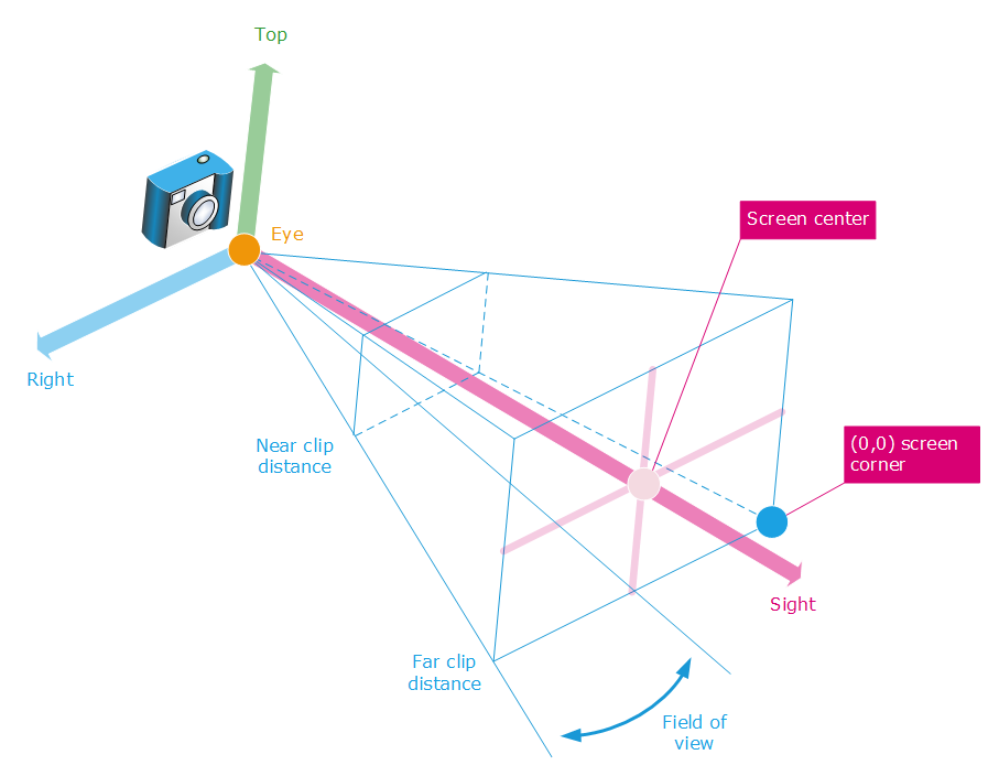
The perspective camera projection model
A perspective camera projection model is set using RED::IViewpoint::SetFrustumPerspective. A perspective camera uses the RED::VPT_PERSPECTIVE projection type, that can be retrieved using RED::IViewpoint::GetProjection. The perspective camera projection model implements perspective foreshortening, using homogenous matrix transformations.
HOOPS Luminate supports asymmetry in its projection models. Asymmetric cameras are mainly used for stereoscopy setup and for tile based rendering of large images.
An asymmetric perspective camera can be specified using RED::IViewpoint::SetAsymmetricFrustumPerspective, using the following specification:
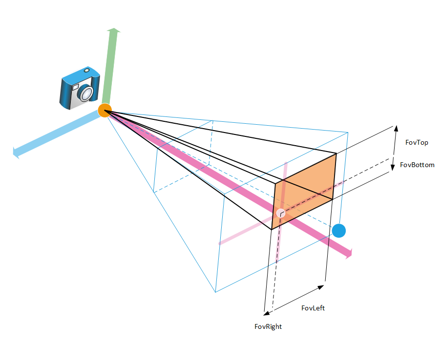
The asymmetric perspective camera projection model
As quoted in the method’s documentation, the definition of each field of view angle is oriented from the screen center.
Orthographic Camera
The RED::IViewpoint interface implements the orthographic camera projection model:
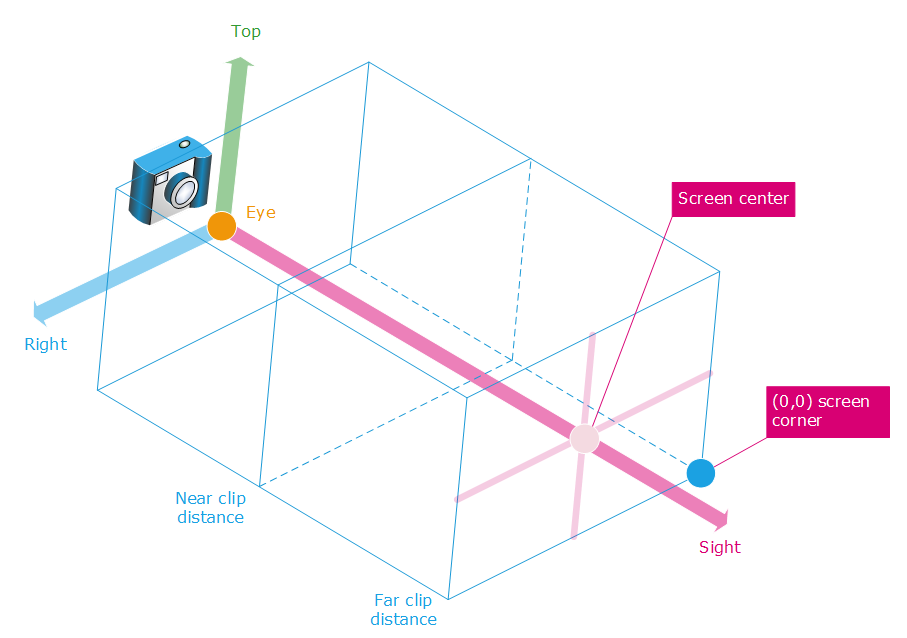
The orthographic camera projection model
An orthographic (or parallel) camera projection model is set using RED::IViewpoint::SetFrustumParallel. A parallel camera uses the RED::VPT_PARALLEL projection type, that can be retrieved using RED::IViewpoint::GetProjection.
Similarly, orthographic cameras can be set asymmetric, using RED::IViewpoint::SetAsymmetricFrustumParallel:
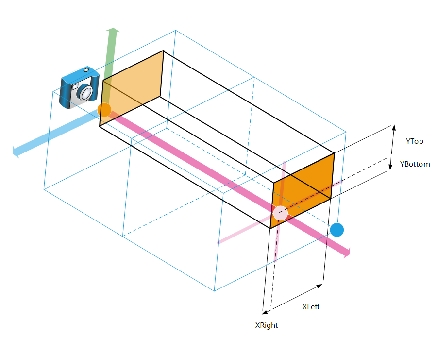
The asymmetric orthographic camera projection model
As quoted in the method’s documentation, the definition of each distance is measured from the screen center.
Custom Camera
HOOPS Luminate lets the application specify its own projection model using RED::IViewpoint::SetFrustumCustom. In this case, the RED::IViewpoint::GetProjection will return the RED::VPT_CUSTOM camera projection type, to indicate that the user has the control over the camera projection model being used.
Orthographic Camera Automatic Eye Shifting
Many shader programs use the eye position internally to define directions or graphic effects. In the case of an orthographic camera projection model, the eye position may remain placed in the center of the scene (and negative near clip distances are allowed in this case!). Therefore, this can cause problems in shading calculations, with some graphic effects that may appear distorted.
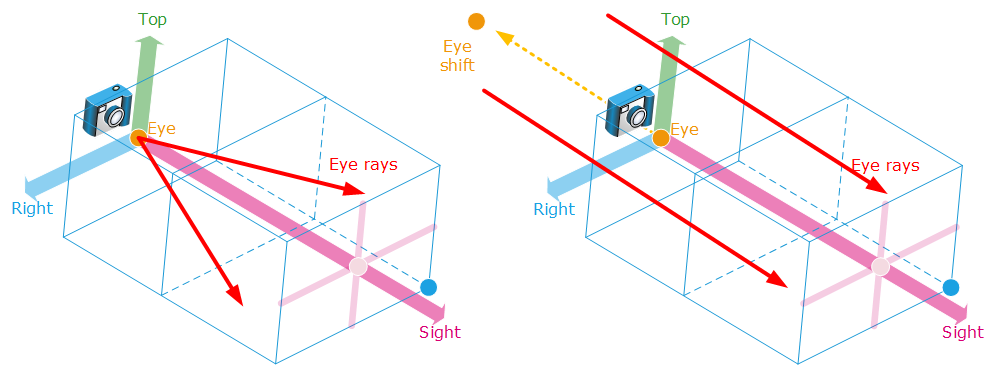
Orthographic viewpoint parallax errors and the automatic eye shifting applied to counter this effect
HOOPS Luminate counter this effect in applying a dynamic shifting of the eye position, negatively along the camera sight vector axis. The eye position is shift backwards of 10.000 model units, unless the RED::OPTIONS_VIEWPOINT_ORTHOGRAPHIC_EYE_AUTO_OFFSET is being disabled for the rendered camera. Note that the shifting does not appear on calling RED::IViewpoint::GetEye. It only appears in the value of the RED::RenderShaderParameter::REF_EYE_POS_WCS reference or in the RED::ISoftRayContext::GetCamera object that can be returned during a software shader query.

