Writing Shaders to Render the Points
In this page, we will describe the shader programs (vertex, geometry and pixels) used to render the point shapes. The side application contains two tests with their own shader programs:
- The first and easiest one draws the points in camera space (billboards)
- The second one draws the shapes in object space using a normal
All the shader programs are written in GLSL.
Note
As there are geometry shaders, please be sure that your graphic card supports the OpenGL 3.2 version and that your drivers are correctly updated to run the demo.
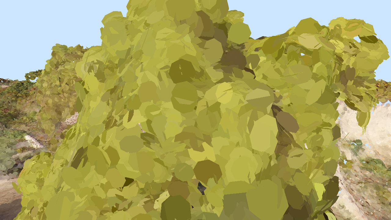
Billboard Shapes
A billboard is a flat shape which always faces the camera. It seems to “rotate” in the scene when the camera moves.
Billboards: all the point shapes look at the camera.
Vertex Shader
The vertex shader is very simple. All it does is transforming the vertices from world space to clip space:
// Transform the vertex.
gl_Position = gl_ModelViewProjectionMatrix * gl_Vertex;
And transferring the vertex color and the point size to the next shader stage via the ‘vertex_out’ structure:
// Transfer the color and the point size.
vertex_out.vColor = gl_Color;
vertex_out.pointSize = min( gl_MultiTexCoord0.x, average_distance * capped_point_size ) * point_size_scale;
The point size calculated during the preparing phase (doc Preparing the Point Shape Data under the Point Shape Data section) is accessed here via the ‘gl_MultiTexCoord0.x’ variable.
Several parameters are used to constrain the point size under a given threshold. The complete formula is explained in the Filtering the Noise page.
A scale factor is also applied via the ‘point_size_scale’ variable. It allows the user to dynamically increase or decrease the point size at runtime.
Geometry Shader
The most important part of the drawing algorithm is situated in the geometry shader. The geometry program takes the point primitives as input and transforms them in a triangle strip to render the desired shapes (quad or octagon).
Geometry shader in and out definition for the quad version:
layout( points ) in;
layout( triangle_strip, max_vertices = 4 ) out;
The point size is retrieved from the input vertex:
// Retrieve the point size.
float d = vertex_in[0].pointSize;
For the quad version, 4 new vertices are defined around the original point. An output vertex is defined by its position and its colour. As we want the shapes to be defined in camera space, the offset is multiplied by the projection matrix which transforms the camera space to the output clip space.

From object space to device space transformations stages
// Offset the vertex in camera space.
vec4 offset = gl_ProjectionMatrix * vec4( -d, -d, 0.0, 0.0 );
gl_Position = gl_in[ 0 ].gl_Position + offset;

// Transfer the color and texture coordinates to the pixel shader.
vertex_out.vColor = vertex_in[ 0 ].vColor;
vertex_out.vTexCoord = vec2( 0.0, 0.0 );
Optional texture coordinates are calculated. This could allow to map a texture image to the shape during the pixel shader stage eventually.
For the octagon version, 8 new vertices have to be defined like this.
Each new vertex of the triangle strip is sent to the GPU via the EmitVertex function. The triangle strip is validated with the EndPrimitive function.
Pixel Shader
The pixel shader is the simplest of the three programs. It just gets the colour of the input pixel and outputs it:
gl_FragColor = vertex_in.vColor;
gl_FragColor.a = 1.0;
There is no transparency, the alpha channel is set to 1.0.
At this stage, we could have get the previously calculated texture coordinates and map a texture.
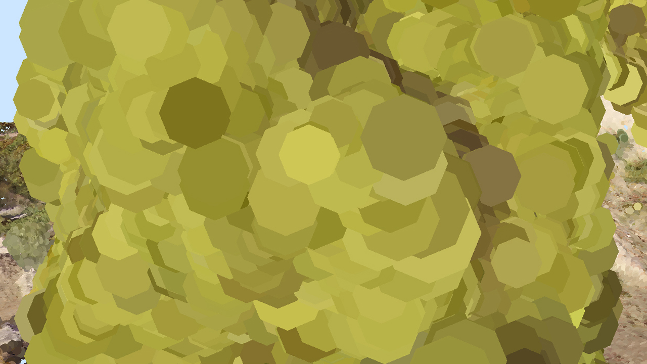
Static Shapes
The second test draws points as static shapes. They are no longer computed in camera space but in object space. They do not move with the camera. In this case, the point normals have to be calculated so that the shapes could be correctly oriented.
The shapes are no longer facing the camera but follow the normal
Finding the Normal
The normal vector to a point is calculating with the help of its neighbours. Fortunately, the k-d tree structure is still there to give us a list of the n neighbours of a point (How to Handle Efficiently the High Number of Points? under section Using a k-d Tree). Finding the normal to a set of points is equivalent to finding the best fitting plane and is not an easy task. Analytical methods such as least-squares fit exists but will not be covered in this book.
In the application, we wrote a much simpler brute-force algorithm to find a correct plane. We loop through n possible normals in spherical coordinates and keep the best one (minimizing a computed error value). To fasten the operation, the sine/cosine table for all the needed values is computed at initialization.
The plane position is defined by the average position of the points. No difficulty here.
The brute-force algorithm around the sphere to find the normal:
// Compute planes around phi and theta in spherical coordinates.
// phii from 0 to pi/2. Only z-up normals needed.
// theta from 0 to 2pi.
for( int phii = 0; phii < POINT_CLOUD_SIN_SIZE / 4; ++phii )
{
    for( int thetai = 0; thetai < POINT_CLOUD_SIN_SIZE; ++thetai )
    {
        // Cosine is given by cos(x) = sin(x + pi/2)
        plane[0] = g_sin[ phii ] * g_sin[ thetai + POINT_CLOUD_COS_OFFSET ];
        plane[1] = g_sin[ phii ] * g_sin[ thetai ];
        plane[2] = g_sin[ phii + POINT_CLOUD_COS_OFFSET ];
        plane[3] = p[0] * plane[0] + p[1] * plane[1] + p[2] * plane[2];

        // Compute the cumulated distance/error between the points and the plane.
        err = 0.0;
        for( unsigned int i = 0; i < count; ++i )
        {
            dist = points[ i * padding + 0 ] * plane[0] + points[ i * padding + 1 ] * plane[1] + points[ i * padding + 2 ] * plane[2] - plane[3];
            err += dist * dist;
        }

        // Save the plane with the minimum error.
        if( err < min_err )
        {
            min_err = err;
            coeff[0] = plane[0];
            coeff[1] = plane[1];
            coeff[2] = plane[2];
            coeff[3] = plane[3];

            if( err == 0.0 )
                return RED_OK;
        }
    }
}
The drawback of this method is that closed points could have the same normal resulting in the superposition of the shapes and in ‘z-fighting’. Z-fighting induces visual artefacts and blinking triangles. To avoid that a small random tilt is applied to the normals using the RED::FastRandom class.
// Tilt the normal to avoid z-fighting between planes.
// The tilt angle lays between -0.05 and 0.05 rad around x and y axis.
jitangle[0] = ( ( (double)randomizer.Rand32() / (double)RED::RNG::Max32 ) * 2.0 - 1.0 ) * 0.05;
jitangle[1] = ( ( (double)randomizer.Rand32() / (double)RED::RNG::Max32 ) * 2.0 - 1.0 ) * 0.05;
jitter.RotationAngleMatrix( RED::Vector3::ZERO, (float)jitangle[0], (float)jitangle[1], 0.0 );
jitter.RotateNormalize( plane, plane );
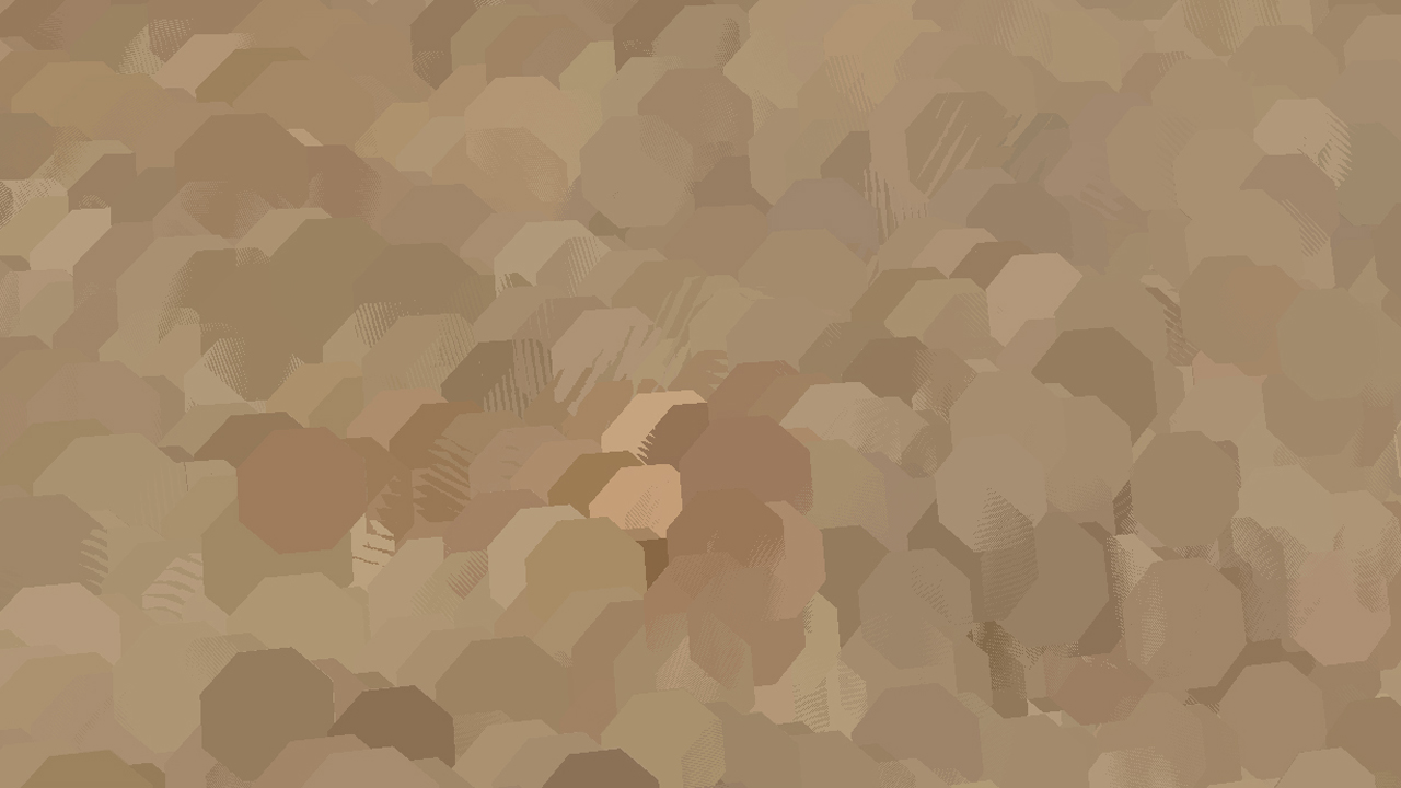
Shapes without tilted normal resulting in z-fighting
The normal is transmitted to the vertex shader via the RED::MCL_NORMAL mesh channel of our point shapes in the same way as the position and color (see Preparing the Point Shape Data).
Updating the Shader Programs
The shader programs need to be updated to accept normals and to build shapes with them.
In the vertex shader, a few lines are added to transfer the new normal data:
// Multiply by the world inverse transpose matrix to get the correct normal in world space.
vec4 nor = gl_TextureMatrixInverseTranspose[1] * vec4( gl_Normal.xyz, 1.0 );
vertex_out.vNormal = nor.xyz;
The important part is still in the geometry shader. First of all, the tangent space needs to be computed. You can either build it before the rendering and send it to the shader, or build it directly in the shader at runtime. The last option is described here. From the normal and an arbitrary unit vector (x), a transform matrix is built:
// Build tangent space.
vec3 basez = vertex_in[0].vNormal;
vec3 basey = normalize( vec3( 0.0, basez.z, -basez.y ) );
vec3 basex = cross( basey, basez );
mat4 base;
base[0] = vec4( basex.x, basex.y, basex.z, 0.0 );
base[1] = vec4( basey.x, basey.y, basey.z, 0.0 );
base[2] = vec4( basez.x, basez.y, basez.z, 0.0 );
base[3] = vec4( 0.0, 0.0, 0.0, 1.0 );
Each vertex of the quad (or the octagon) is then built by applying an offset to the point in the tangent space of the point. The output must still be in clip space, that is why this transformation is done:n Projection matrix * View matrix * World matrix * Tangent space matrix:
// Offset the vertex in tangent space.
offset = gl_ModelViewProjectionMatrix * base * vec4( d, d, 0.0, 0.0 );
gl_Position = gl_in[ 0 ].gl_Position + offset;

// Transfer the color and texture coordinates to the pixel shader.
vertex_out.vColor = vertex_in[ 0 ].vColor;
vertex_out.vTexCoord = vec2( 1.0, 1.0 );
The fragment shader program does not change. It still gets the point color and draws it.

